Pet bottles have strong applicability and are widely used in daily necessities, daily chemical packaging and other fields. Due to the light weight, good storage, and the technical trend of emphasizing heat resistance and pressure resistance, pet bottles have become the mainstream of today's drinking packaging. Because pet macromolecules contain fat base and have certain hydrophilicity, pellets are more sensitive to water at high temperature. When the moisture content exceeds the limit, the molecular weight of pet will decrease during processing, and the product will become colored and brittle. Therefore, the material must be dried before processing.
The raw materials used to produce pet bottles are flake particles, which are packaged and transported in bags. A common practice in this field is to use a dryer to dry the pet particles, and use a vacuum pump or a centrifugal pump to pump the bagged particles placed on the ground to the top of the dryer to enter the dryer for drying. The existing method causes pet particles to remain at the bottom of the material bag every time the material is pumped, which requires manual processing, which requires a lot of manpower and time, and greatly increases production costs.
At present, in the existing field, there is no drying device for feeding bagged pet particles, and its material utilization rate and production efficiency are low.
Technical realization elements:
plastic dryer, Dehumidifying dryer, serin dryer, plastic Dehumidifying dryer
The purpose of the utility model is to provide a drying device for bagged pet particles, which solves the problem of incomplete feeding of the bagged pet particles during drying.
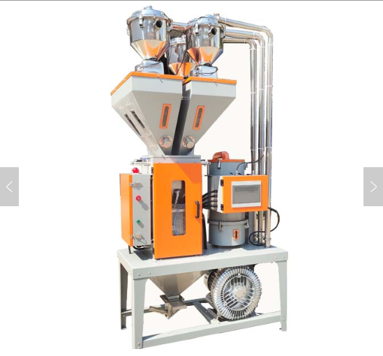
The technical solution provided by the utility model is: a drying device for bagged pet particles, including a drying tank for drying the particles, a hot air blower for providing the heat source of the drying tank, and the drying tank is provided with The feeding unit for feeding the material bag, the feeding unit includes a hanger for hanging the material bag, a funnel for collecting particles, a box for storing particles, a hose connecting the box and the dryer, and a hose for extracting particles. Vacuum pump;
One side of the pendant is connected to the middle of the drying tank; the funnel is arranged directly below the pendant; the discharge end of the funnel is connected to the upper side of the box; the bottom of the box The side is provided with a discharge port, the discharge port is fixedly connected to one end of the hose, and the other end of the hose is fixedly connected to the feed port on the top of the drying tank; the middle of the funnel is provided with an upward protruding Leaking part, a plurality of leakage holes are arranged on the side wall of the leaking part.
In the above-mentioned drying device for bagged pet particles, the leaked material has a tapered structure that is placed; the bottom of the leaked material is welded to the inner wall of the funnel, and the top of the leaked material At the same vertical height as the top of the funnel.
In the above-mentioned drying device for bagged pet particles, an openable and closable end cap is provided on the feed end of the funnel, and the end cap adopts a double-open structure; the outer side of the funnel is provided with a vibrator .
In the above-mentioned drying device for bagged pet particles, the leakage hole is arranged at the lower part of the leakage member; the leakage hole is in the shape of a strip, and the upper end diameter of the leakage hole is smaller than the lower end diameter.
In the above drying device for bagged pet particles, the pendant includes a supporting part and a hook; the supporting part is a rectangular frame, and a plurality of angle irons are arranged in the frame;
The side of the frame away from the drying tank is provided with a support column that is in contact with the ground;
The inner sides of the corners of the frame are provided with hooks, and the hooks respectively face the outer side of the frame.
In the above drying device for bagged pet particles, the upper side of the frame is provided with a transparent acrylic plate, and the acrylic plate is bolted to the frame; the surface of the acrylic plate is larger than the material of the bag The diameter of the mouth.
In the above-mentioned drying device for bagged pet particles, the box body is provided with a magnetic frame for adsorbing metal dust, and the magnetic frame is set flat directly above the discharge port of the box body; The cross section of the magnetic stand is larger than the diameter of the discharge port of the box.
plastic dryer, Dehumidifying dryer, serin dryer, plastic Dehumidifying dryer
After adopting the above technical scheme, the present utility model has the following beneficial effects:
As a further improvement, this solution adopts a top-down feeding method by setting up a feeding unit, using gravity to do work, so that the bagged particles in each bag can be completely fed without manual feeding again; the working process is: The bag is hung in the air, and the bottom of the bag is divided and opened by the sharp top of the leaking part. After the hole is opened, the leaking part is deep into the hole. The particles in the bag are guided by the cone surface, and the particles slide to the leak. The bottom of the material enters the leakage hole, enters the inside of the box from the discharge end of the funnel, and then enters the hose from the discharge port on the lower side of the box, and the vacuum pump is turned on to pump pressure, and the particles smoothly enter the drying tank.
As a further improvement, this solution uses the structure of the leaking part to make the top of the tapered leaking part have the function of splitting and piercing. After the bag is hung on the pendant, the bag needs to be squared, and the bottom of the bag is lower than The top of the leaking material is cut open during the continuous swinging and pulling process; by setting the leaking part deep into the material bag, the leaking material also has the function of positioning and guiding the discharge to avoid local flow velocity during the discharge of the material bag Unbalance to prevent clogging of discharge.
As a further improvement, this solution uses end caps to cover the end caps when not in production. The feeding unit is a closed space to prevent foreign matter and dust from entering, avoiding raw material contamination, and is practical; the vibrator is set up to make the funnel slightly vibrate , To further prevent the blockage of the blanking and ensure the smooth passage of the particles.
As a further improvement, in this solution, the upper end aperture of the leakage hole is set, so that when the particles fall from top to bottom, they pass through the upper end of the leakage hole and enter the discharge end of the leakage. Because the upper end of the aperture is set smaller, It can reduce the feeding amount of particles and avoid blocking the discharge end of the funnel; the lower end of the leakage hole is set to make the particles partially blocked in the upper end of the hole are washed to the bottom, and then pass through the larger hole at the bottom Entering the discharge end of the funnel achieves the effect of dividing the flow into the discharge end of the funnel, avoiding clogging and improving production efficiency.
As a further improvement, this solution is practicable by arranging the structure of the hanger, so that the material bag can be suspended in a balanced suspension without tilting the material and causing the particles to spill out. By setting the hooks to face outwards, the material bags are suspended. It can be inserted directly from the outside to the inside, which is simple and quick.
As a further improvement, this solution uses an acrylic plate to cover the material opening of the material bag to prevent foreign matter and dust from falling directly into the material opening of the material bag. It has a certain dustproof function; the transparent acrylic plate is used to make the cutting process In the process, directly observe the inside of the material bag through the acrylic board to check the pellet discharge situation in order to prepare for subsequent bag change.
As a further improvement, this solution is equipped with a magnetic frame, so that the box can not only be used as a storage box for temporary storage of particles, but also has a filtering and adsorption function. The friction between particles generates static electricity and easily absorbs dust and metal powder. The box is discharged first. It is filtered by the magnetic frame to avoid the raw materials mixed with impurities, which is practical.
Description of the drawings
Figure 1 is a schematic diagram of the structure of a drying device for bagged pet particles according to Embodiment 1 of the present invention;
Figure 2 is a schematic structural view of the pendant of Embodiment 1 of the present invention;
Figure 3 is a schematic diagram of the structure of the funnel and the leakage part of the embodiment 1 of the present invention;
Fig. 4 is a schematic diagram of the structure of the box in the first embodiment of the present invention.
plastic dryer, Dehumidifying dryer, serin dryer, plastic Dehumidifying dryer
Reference signs:
1. Acrylic board;
2. Drying tank;
3. Hot air blower;
4. Hose;
5. Vacuum pump;
6. Box body;
7. Funnel;
8. End cover;
9. Angle iron;
10. Hook;
11. Vibrator;
12. Leaking parts;
13. Leakage hole;
14. Magnetic stand.
Detailed ways
The technical solution of the present utility model will be further described in detail below in conjunction with the specific embodiments, but it does not constitute any limitation to the present utility model.
Example 1: As shown in Figures 1-4, a drying device for bagged pet particles includes a drying tank 2 for drying the particles 2 and a hot air blower 3 for providing the heat source of the drying tank 2. The drying tank 2 is provided with a feeding unit for feeding the bag. The feeding unit includes a hanging piece for hanging the bag, a funnel 7 for collecting particles, a box 6 for storing particles, and a connecting box 6 with the dryer. The hose 4 and a vacuum pump 5 for extracting particles on the hose 4;
Wherein, one side of the pendant is connected to the middle of the drying tank 2; the funnel 7 is arranged directly below the pendant; the discharge end of the funnel 7 is connected to the upper side of the box 6; The lower side of the box body 6 is provided with a discharge port, the discharge port is fixedly connected to one end of the hose 4, and the other end of the hose 4 is fixedly connected to the feed port on the top of the drying tank 2; The middle part of the funnel 7 is provided with a leakage member 12 protruding upward, and a plurality of leakage holes 13 are provided on the side wall of the leakage member 12.
The principle is to use gravity to do work and adopt a top-down feeding method, so that the bagged particles in each bag can be fully fed without manual re-feeding; the working process is to hang the bag in the air and use The sharp top of the leaking part 12 splits and opening the bottom of the material bag. After opening the hole, the leaking part 12 is penetrated into the hole. The particles in the material bag slide to the bottom of the leaking part 12 under the guidance of the cone surface. Enter the leakage hole 13, enter the inside of the box 6 from the discharge end of the hopper 7, and then enter the hose 4 at the discharge port on the lower side of the box 6, the vacuum pump 5 is turned on for pumping pressure, and the particles enter the drying tank 2 smoothly.
In this embodiment, the leakage element 12 is a forward-placed tapered structure; the bottom of the leakage element 12 is welded to the inner wall of the funnel 7, and the top of the leakage element 12 is connected to the funnel 7 The top of the material bag is at the same vertical height; the top of the tapered material leakage part 12 has the function of dividing and piercing. After the material bag is hung on the pendant, the material bag needs to be squared. At this time, the bottom of the material bag is lower than that of the material leakage part 12. At the top, the bag is cut open during the continuous swinging and pulling process; by setting the leaking part 12 deep into the bag, the leaking part 12 also has the function of positioning and guiding the discharge to avoid the local flow rate imbalance during the bag discharge process , To prevent unloading from blocking
Preferably, an openable end cover 8 is provided on the feed end of the hopper 7, and the end cover 8 adopts a double-open structure, so that the end cover 8 is covered when not in production, and the feed unit is a closed space to prevent The ingress of foreign matter and dust avoids contamination of raw materials and is practical; the outer side of the funnel 7 is provided with a vibrator 11, so that the funnel 7 and the leakage part 12 can be slightly shaken to further prevent the material from being blocked and ensure the smooth passage of particles.
In practical applications, the material leakage hole 13 is arranged at the lower part of the material leakage member 12; the material leakage hole 13 is in the shape of a strip, and the upper end diameter of the material leakage hole 13 is smaller than the lower end diameter, so that the particles are In the process of falling from top to bottom, first enter the discharge end of the leakage through the upper end of the leakage hole 13. Since the upper end of the aperture is set to be smaller, the feed amount of particles can be reduced, and the discharge end of the funnel 7 can be prevented from being blocked; The lower end aperture of the material hole 13 is set so that the particles partially blocked in the upper end aperture are washed to the bottom, and then enter the discharge end of the funnel 7 through the leakage hole 13 with a larger aperture at the bottom, and reach the split flow into the funnel 7 The effect of the discharge end avoids clogging and improves production efficiency.
In this embodiment, the pendant includes a supporting part and a hook 10; the supporting part is a rectangular frame, and a plurality of angle irons 9 are arranged in the frame; the part of the frame is far from the drying tank 2 One side is provided with a support column contacting the ground; the inner corners of the frame are all provided with hooks 10, and the hooks 10 respectively face the outer side of the frame.
Preferably, by setting the structure of the hanging part, the material bag can be suspended in a balanced way without tilting the material, causing particles to spill, which is practical; by setting the hooks 10 to face outwards respectively, the material bags can be hung directly. It is easy and quick to insert directly from the outside to the inside.
As a further improvement, a transparent acrylic plate 1 is provided on the upper side of the frame, and the acrylic plate 1 is bolted to the frame; the surface of the acrylic plate 1 is larger than the diameter of the material opening of the material bag, so that The material mouth of the material bag is fully covered to prevent foreign matter and dust from falling directly into the material mouth of the material bag, which has a certain dustproof function; the transparent acrylic plate 1 is used, so that the material bag can be directly observed through the acrylic plate 1 during the cutting process Inside, check the pellet discharge situation for subsequent bag change preparations.
In addition, the box body 6 is provided with a magnetic frame 14 for adsorbing metal dust. The magnetic frame 14 is flatly arranged directly above the discharge port of the box body 6; the cross-section of the magnetic frame 14 is larger than The diameter of the discharge port of the box 6 makes the box 6 not only a storage box for temporary storage of particles, but also has a filtering and adsorption function. The friction between particles generates static electricity and easily absorbs dust and metal powder. When the box 6 is discharged It is filtered through the magnetic frame 14 first to prevent the raw materials from being mixed with impurities, which is practical.
The above-mentioned embodiments are preferred embodiments of the utility model, but the embodiments of the utility model are not limited by the above-mentioned embodiments, and any other changes, modifications, and substitutions made without departing from the spirit and principle of the utility model , Combination, and simplification should all be equivalent replacement methods, which are all included in the protection scope of the present invention.


 +8613669807274
 +8613669807274
 wto-btb@wto-btb.com
 Tel: +8613669807274
 SMS: +8613669807274